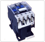
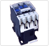
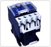
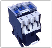
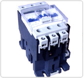
MC1-D AC Contactors
|
|
|
|
|
MC1-D-09/12 |
MC1-D-18 |
MC1-D-25 |
|
Environment |
|
Type |
|
MC1-D
09...18
T20&T25 |
MC1-D
25...38
T32&T40 |
MC1-D
40 |
MC1-D
50...95 |
MC1-D115&MC1-D150 |
|
Rated insulation voltage (Ui) |
Conforming to IEC 947-4-1,overvoltage category III,degree of pollution:3 |
690V |
690V |
690V |
690V |
690V |
|
Rated impulse withstand voltage(Uimp) |
Conforming to IEC947 |
6kV |
6kV |
8kV |
8kV |
8kV |
|
Conforming to standards |
|
IEC947-1,947-4-1,EN 60947-1,60947-4-1 |
|
Degree of protection(1) |
Power connection |
Protection against direct finger contact IP2X |
|
Front face only |
Coil connection |
Protection against direct finger contact IP 2X(except MC1-D40...80 |
|
Protective treatment |
Conforming to IEC68 |
"TH" |
|
Ambient air temperature |
Storage |
-60...+80 ? |
|
Around the device |
Operation |
-5...+60? |
|
|
Permissible |
-40...+70?,for operation at Uc |
|
Maximum operating altitude |
Without derating |
3000m |
|
Operating position |
Without derating |
�30�possible, in relation to normal vertical mounting plane |
|
Flame resistance |
Conforming to IEC 695-2-1 |
960? |
|
Shock resistance(2) |
Contactor open |
10gn |
8gn |
8gn |
8gn |
6gn |
|
1/2 sine wave=11HM |
Contactor closed |
15gn |
15gn |
10gn |
10gn |
15gn |
|
Vibration resistance(2) |
Contactor open |
2gn |
2gn |
2gn |
2gn |
2gn |
|
5...300Hz |
Contactor closed |
4gn |
4gn |
4gn |
3gn |
4gn |
|
|
(1), Protection ensured for the connection cross-sections shown on the nex t page and for connection via cable
(2), In the least favourable direction,without change of contact state(coil supplied at Ue) |
|
Power circuit connections-Connection via cable
|
Type |
MC1-D |
09&12
T20&T25 |
18(3P) |
25 |
32&38 |
18&25(4P) T32&T10 |
40 |
50&65 |
80&95 |
115&150 |
|
Tightening |
|
Screw clamps |
2-input cnnector |
Screw clamps |
1-input connector |
2-input connector |
|
Flexible cable without cable end (mm2) |
1 conductor |
1...4 |
1.5...6 |
1.5...10 |
2.5...10 |
2.5...10 |
2.5...25 |
2.5...25 |
4...50 |
10...120 |
|
2 conductor |
1..4 |
1.5...6 |
1.5...6 |
2.5...10 |
2.5...10 |
2.5...16 |
2.5...16 |
4...25 |
10...120+10...50 |
|
Fiexible cable with cable end (mm2) |
1 conductor |
1...4 |
1...6 |
1...6 |
1...10 |
2.5...10 |
2.5...25 |
2.5...25 |
4...50 |
10...120 |
|
2 conductor |
1...2.5 |
1...4 |
1...4 |
1.5...6 |
2.5...10 |
2.5...10 |
2.5...10 |
4...16 |
10...120+10...50 |
|
Solid cable without cable end (mm2) |
1 conductor |
1...4 |
1.5...6 |
1.5...6 |
1.5...10 |
2.5...16 |
2.5...25 |
2.5...25 |
4...50 |
10...120 |
|
2 conductor |
1...4 |
1.5...6 |
15....6 |
2.5...10 |
2.5...16 |
2.5...16 |
2.5...16 |
4...25 |
10...120+10...50 |
|
Screwdriver |
Head |
N�2 |
N�2 |
N�2 |
N�2 |
N�2 |
-- |
-- |
-- |
-- |
|
? flat screwdrive |
?6 |
?6 |
?6 |
?6 |
?6 |
?6...?8 |
?6...?8 |
?6...?8 |
-- |
|
6 sided key |
-- |
-- |
-- |
-- |
-- |
-- |
-- |
4 |
4 |
|
Tightenning torque (N.m) |
1.7 |
1.7 |
2.5 |
2.5 |
1.8 |
5 |
|
9 |
12 |
|
Connection via spring terminals(2) |
|
Flexibl cable without cable end (mm2) |
1 conductor |
2.5(4:T25) |
4 |
4 |
4 |
-- |
10 |
-- |
-- |
|
|
2 conductor |
2.5(except T25:-) |
4 |
4 |
4 |
-- |
-- |
--- |
-- |
|
|
Connection via bars or lugs |
|
Bar cross-section |
-- |
-- |
-- |
-- |
-- |
-- |
-- |
-- |
-- |
|
Lug external ? |
8 |
8 |
10 |
10 |
8(1) |
13 |
16 |
17 |
25 |
|
? of screw |
M3.5 |
M3.5 |
M4 |
M4 |
M3.5 |
M5 |
M6 |
M6 |
M8 |
|
Screwdriver |
Head |
N�2 |
N�2 |
N�2 |
N�2 |
N�2 |
N�2 |
N�2 |
-- |
-- |
|
?flat screwdriver |
?6 |
?6 |
?6 |
?6 |
?6 |
?8 |
?8 |
?8 |
-- |
|
Key for hexagonal headed screw |
-- |
-- |
-- |
-- |
-- |
-- |
-- |
10 |
13 |
|
Tightening torque |
1.7 |
1.7 |
2.5 |
2.5 |
1.8 |
5 |
5 |
9 |
12 |
Power circuit connections-Connection via cable(tightening via screw clamps) |
|
Type |
MC1-D |
09&12
T20&T25 |
18(3P) |
25 |
32&38 |
18&25(4P) T32&T10 |
40 |
50&65 |
80&95 |
115&150 |
|
Flexible cable without cable end (mm2) |
1 conductor |
1...4 |
1..4 |
1...4 |
1...4 |
1...4 |
1...4 |
1...4 |
1...4 |
1...2.5 |
|
2 conductor |
1...4 |
1...4 |
1...4 |
1...4 |
1...4 |
1...4 |
1...4 |
1...4 |
1...2.5 |
|
Fiexible cable with cable end (mm2) |
1 conductor |
1...4 |
1...4 |
1...4 |
1...4 |
1...4 |
1...2.5 |
1...2.5 |
1...2.5 |
1...2.5 |
|
2 conductor |
1..2.5 |
1...2.5 |
1...2.5 |
1...2.5 |
1...2.5 |
1...2.5 |
1...2.5 |
1...2.5 |
1...2.5 |
|
Solid cable without cable end (mm2) |
1 conductor |
1...4 |
1...4 |
1...4 |
1...4 |
1...4 |
1...4 |
1...4 |
1...4 |
1...2.5 |
|
2 conductor |
1...4 |
1...4 |
1...4 |
1...4 |
1...4 |
1...4 |
1...4 |
1...4 |
1...2.5 |
|
Screwdriver |
Head |
N�2 |
N�2 |
N�2 |
N�2 |
N�2 |
N�2 |
N�2 |
N�2 |
N�2 |
|
? flat screwdrive |
?6 |
?6 |
?6 |
?6 |
?6 |
?6 |
?6 |
?6 |
?6 |
|
Tightenning torque (N.m) |
1.7 |
1.7 |
1.7 |
1.7 |
1.7 |
1.2 |
1.2 |
1.2 |
1.2 |
|
Connection via spring terminals(2) |
|
Flexibl cable without cable end (mm2) |
1 conductor |
2.5 |
2.5 |
2.5 |
2.5 -- |
2.5 |
-- |
-- |
-- |
-- |
|
2 conductor |
2.5 |
2.5 |
2.5 |
2.5 -- |
2.5 |
-- |
--- |
-- |
-- |
|
Connection via bars or lugs |
|
Lug external ? (mm) |
8 |
8 |
10 |
10 |
8 |
13 |
16 |
17 |
25 |
|
? of screw (mm) |
M3.5 |
M3.5 |
M3.5 |
M3.5 |
M3.5 |
M3.5 |
M3.5 |
M3.5 |
M3.5 |
|
Screwdriver |
Head |
N�2 |
N�2 |
N�2 |
N�2 |
N�2 |
N�2 |
N�2 |
N�2 |
N�2 |
|
?flat screwdriver |
?6 |
?6 |
?6 |
?6 |
?6 |
?6 |
?6 |
?6 |
?6 |
|
Tightening torque (N.m) |
1.7 |
1.7 |
1.7 |
1.7 |
1.7 |
1.2 |
1.2 |
1.2 |
1.2 |
|
|
(1) To connect cables with a c.s.a.>4mm2 and up to 10mm2 ,it is essential to use spectial connectors ,sold in bags lf 100 (reference:MC1-D-961860)
(2) If cable ends are used, choose the next size down (example: for 2.5 mm2,use 1.5mm2 )and square crimp the cable ends using a special tool |
|
|
|
|
|
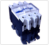
MC1-D-32 |
MC1-D-40/50/65 |
MC1-D-80/95 |
|
Pole characteristics |
|
Type |
MC1-D- |
09
(3P) |
T20
&098 |
12
(3P) |
T25&125 |
18(3P) |
T32&188 |
25(3P) |
T40&258 |
32 |
38 |
|
Rated operational current(le)
(Ue=440V) ( A) |
In AC-3,?=60? |
9 |
9 |
12 |
12 |
18 |
18 |
25 |
25 |
32 |
38 |
|
In AC-1,?=60? |
25(1) |
20 |
25(1) |
25 |
32(1) |
32 |
40(1) |
40 |
50(1) |
50 |
|
Rated operational voltage(Ue) ( V ) |
Up to |
690 |
690 |
690 |
690 |
690 |
690 |
|
Frequency limits ( Hz) |
Of the operating current |
25...400 |
25...400 |
25...400 |
25...400 |
25...400 |
25...400 |
|
Conventional thermal current(lth) |
?=60? |
25(1) |
20 |
25(1) |
25 |
32(1) |
32 |
40(1) |
40 |
50 |
50 |
|
Rated making capacity(440V) |
Conforming to IEC 947 |
250 |
250 |
300 |
450 |
550 |
550 |
|
Rated breaking capacity(440V) |
Conforming to IEC 947 |
250 |
250 |
300 |
450 |
550 |
550 |
|
Permissible short-time rating
No current flowing for preceding
15 minutes at ? =40? |
For 1 s |
210 |
210 |
240 |
380 |
430 |
430 |
|
For 10 s |
105 |
105 |
145 |
240 |
260 |
310 |
|
For 1min |
61 |
61 |
84 |
120 |
138 |
150 |
|
For 10 min |
30 |
30 |
40 |
50 |
60 |
60 |
|
Protection by fuse against
short-circuits(U=690V) |
Without thermal type 1 |
25 |
40 |
50 |
63 |
63 |
63 |
|
Overload relay,fuse gG type 1 |
20 |
25 |
35 |
40 |
63 |
63 |
|
With thermal overload relay |
See pages 24514/2 and 24514/3, for aM or gG fuse ratings corresponding to the associated thermal overload relay |
|
Average impedance per pole (WO) |
At lth and 50Hz |
2.5 |
2.5 |
2.5 |
2 |
2 |
2 |
|
Power dissipation per pole for |
AC-3(W) |
0.20 |
0.36 |
0.8 |
1.25 |
2 |
3 |
|
The above operating currents |
AC-1 (W) |
1.56 |
1.56 |
2.5 |
3.2 |
5 |
5 |
a.c. control circuit characteristics
|
Rated control circuit voltage(Uc) |
50/60Hz |
V |
12...690 |
|
Control voltage limits |
50 or 60 Hz coils |
Operational |
|
- |
|
50/60 Hz coils |
Drop-out |
|
- |
|
|
Operational |
VA |
0.8...1.1 Uc on 50 Hz and 0.85...1.1 Uc on 60 Hz at 60? |
|
Drop-out |
|
0.3...0.6 Uc at 60 ? |
|
Average consumption
at 20? and at Uc |
~50Hz |
Inrush |
50 Hz coil |
VA |
- |
|
Cosf |
|
0.75 |
|
50/60 Hz coil |
VA |
70 |
|
Sealed |
50 Hz coil |
VA |
- |
|
Cosf |
|
0.3 |
|
50/60 Hz coil |
VA |
7 |
|
~60Hz |
Inrush |
50 Hz coil |
VA |
- |
|
Cosf |
|
0.75 |
|
50/60 Hz coil |
VA |
70 |
|
Sealed |
|
VA |
- |
|
Cosf |
|
0.3 |
|
50/60 Hz coil |
VA |
7.5 |
|
Heat dissipation 50/60 Hz |
|
W |
2...3 |
|
Operating time(2) |
Closing "C" |
ms |
12...22 |
|
Opening "O" |
ms |
4...19 |
|
Mechanical life
in millions of operating cycles |
50 or 60 Hz coil |
|
- |
|
50/60 Hz coil on 50 Hz |
|
15 |
|
Maximum operating rate
at ambient temperature =60? |
In operating cycles per hour |
|
3600 |
|
|
(1) Versions with spring terminal connections:20A for MC1-D-093 and MC1-D-123,25A for MC1-D-183 to MC1-D323,32A for MC1-D183 connected with 2� 4mm 2 cable in parallel,40A for MC1-D253 and MC1-D323 connected with 2�4 mm 2 cables in parallel.
(2) The closing time "C" is measured from the moment the coil supply is swithed on to initial contact of the main poles.The opening time"O" is measured from the moment the coil supply is switched off to the moment the main poles separate. |
|
Pole characteristics
|
Type of contactor |
MC1-D- |
D40 |
D50 |
D65 |
D80 |
D95 |
|
Rated operational current(te)
(Ue=440V) |
In AC-3,?=60? |
A |
40 |
50 |
65 |
80 |
95 |
|
In AC-1,?=60? |
A |
60 |
80 |
80 |
125 |
125 |
|
Rated operational voltage(Ue) |
Up to |
V |
1000 |
1000 |
1000 |
1000 |
1000 |
|
Frequency limits |
Of the operating current |
Hz |
25...400 |
25...400 |
25...400 |
25...400 |
25...400 |
|
Conventional thermal current(1th) |
?=60? |
A |
60 |
80 |
80 |
125 |
125 |
|
Rated making capacity(440V) |
Conforming to IEC 947 |
|
800 |
900 |
1000 |
1100 |
1100 |
|
Rated breaking capacity(440V) |
Conforming to IEC 947 |
|
800 |
900 |
1000 |
1100 |
1100 |
|
Permissible short-time rating
No current flowing for preceding
15 minutes at ?=40? |
For 1 s |
A |
720 |
810 |
900 |
990 |
1100 |
|
For 10 s |
A |
320 |
400 |
520 |
640 |
800 |
|
For 1min |
A |
165 |
208 |
260 |
320 |
400 |
|
For 10 min |
A |
72 |
84 |
110 |
135 |
135 |
|
Protection by fuse against
short-circuits(U=690V) |
Without thermal type 1 |
A |
80 |
100 |
160 |
200 |
200 |
|
Overload relay,fuse gG type 1 |
A |
80 |
100 |
125 |
160 |
160 |
|
With thermal overload relay |
A |
See pages 245 14/2 and 245 14/3,for aM or gG fuse ratings corresponding to the associated thermal overload relay |
|
Average impedance per pole |
At 1th and 50Hz |
mO |
1.5 |
1.5 |
1 |
0.8 |
0.8 |
|
0.6Power dissipation per pole for |
AC-3 |
W |
2.4 |
3.7 |
4.2 |
5.1 |
7.2 |
|
13.5The above operating currents |
AC-1 |
W |
5.4 |
9.6 |
6.4 |
12.5 |
12.5 |
|
a.c.control circuit characteristics |
|
Rated control circuit voltage(Uc) |
50/60Hz |
V |
24...660 |
20...500 |
|
Control voltage limits |
50 or 60 Hz coils |
Operational |
|
0.85...1.1Uca t 55 ? |
0.85...1.1Uca t 55 ? |
|
50/60 Hz coils |
Drop-out |
|
0.3...0.6Uc at 55? |
0.3...0.5Uca t 55 ? |
|
|
Operational |
VA |
0.8...1.1 Uc on 50 Hz and 0.85...1.1 Uc on 60 Hz at 55? |
0.8...1.1 Uc on 50/60 Hz at 55 ? |
|
Drop-out |
|
0.3...0.6 Uc at 55 ? |
0.3...0.6 Uc at 55 ? |
|
Average consumption
at 20? and at Uc |
~50Hz |
Inrush |
50 Hz coil |
VA |
200 |
300 |
- |
|
Cosf |
|
0.75 |
0.8 |
0.9 |
|
50/60 Hz coil |
VA |
245 |
280...350 |
280...350 |
|
Sealed |
50 Hz coil |
VA |
20 |
22 |
- |
|
Cosf |
|
0.3 |
0.3 |
0.9 |
|
50/60 Hz coil |
VA |
26 |
2...18 |
2...18 |
|
~60Hz |
Inrush |
50 Hz coil |
VA |
220 |
300 |
- |
|
Cosf |
|
0.75 |
0.8 |
0.9 |
|
50/60 Hz coil |
VA |
245 |
280...350 |
280-350 |
|
Sealed |
|
VA |
22 |
22 |
- |
|
Cosf |
|
0.3 |
0.3 |
0.9 |
|
50/60 Hz coil |
VA |
26 |
2...18 |
2...18 |
|
Heat dissipation 50/60 Hz |
|
W |
6...10 |
3...8 |
3...4.5 |
|
Operating time(2) |
Closing "C" |
ms |
20...26 |
20...26 |
20...26 |
20...35 |
20...35 |
20...50 |
20...35 |
|
Opening "O" |
ms |
8...12 |
8...12 |
8...12 |
6...20 |
6...20 |
6...20 |
40...75 |
|
Mechanical life
in millions of operating cycles |
50 or 60 Hz coil |
|
16 |
16 |
16 |
10 |
10 |
8 |
- |
|
50/60 Hz coil on 50 Hz |
|
6 |
6 |
6 |
4 |
4 |
8 |
8 |
|
Maximum operating rate
at ambient temperature =60? |
In operating cycles per hour |
|
3600 |
3600 |
3600 |
3600 |
3600 |
2400 |
1200 |
|
|
(1) Versions with spring terminal connections:20A for MC1-D-093 and MC1-D-123,25A forMC1-D-183 to MC1-D-323,32A for MC1-D-183 connected with 2� 4mm2 cable in parallel,40A for MC1-D-253 and MC1-D-323 connected with 2�4mm2 cables in parallel. |
|
Pole characteristics |
|
Type |
MC1-D09...38,T20...T40 |
MC1-D-40...65 |
MC1-D |
MC1-D115&
MC1-D-150 |
|
Rated control circuit voltage(Uc) (V) |
12...440 |
12...440 |
12...440 |
24...440 |
|
Rated insulation voltage(Conforming to IEC 947-1) (V) |
690 |
690<, /P> |
690 |
69. |
|
Control voltage limits |
Operatipnal |
Standard coil |
0.7..1.25Uc
at 60? |
0.85...1.1Uc
at 55 ? |
0.85...1.1Uc
at 55 ? |
0.75...1.2Uc
at 55 ? |
|
Wide range coil |
-- |
0.75...1.2Uc
at 55? |
0.75...1.2Uc
at 55? |
-- |
|
Drop-out |
|
0.1...0.25 Uc
at 60 ? |
0.1...0.3Uc
at 55? |
0.1...0.3Uc
at 55? |
0.15...0.4Uc
at 55? |
|
Average consumption at 20? and at Uc (W) |
= |
Inrush |
5.4 |
22 |
22 |
270 to 365 |
|
Sealed |
5.4 |
22 |
22 |
2.4...5.1 |
|
Average operating time (1) at Uc (ms) |
Closing ("C") |
55 |
85...110 |
95...130 |
20...35 |
|
Opening ("O") |
20 |
20...35 |
20...35 |
40...75 |
|
Note:the arcing time depends on the circuit switched by the poles. For normal 3-phase applications ,the arcing time is ususlly less than 10ms .the load is isolated form the supply after a time equal to the sum of the opening time and the arcing time |
|
Time constant(L/R) (ms) |
28 |
65 |
75 |
25 |
|
Mechanical life Uc |
In millions of operation cycles |
30 |
20 |
20 |
8 |
|
Meximum operating rate at ambient temperature =60? |
In operating cycles per hour |
3600 |
3600 |
3600 |
3600 |
Low consumption control circuit characteristics |
|
Rated insulation voltage |
Conforming to IEC 947-1 |
V |
690 |
-- |
-- |
-- |
|
Maximun voltage |
Of the control circuit on = |
|
250 |
-- |
-- |
-- |
|
Average consumption
d.c.at 20? and at Uc |
Wide range coil(0.7...1.25Uc) |
inrush |
W |
2.4 |
-- |
-- |
-- |
|
Sealed |
W |
2.4 |
-- |
-- |
-- |
|
Operating time (1) at Uc and at 20? |
Closing |
"C" |
ms |
70 |
-- |
-- |
-- |
|
opening |
"O" |
ms |
25 |
-- |
-- |
-- |
|
Voltage limits (?=60?) of the control circuit |
Operational |
|
0.7 to 1.25 Uc |
-- |
-- |
-- |
|
Drop-out |
|
0.1...0.3 Uc |
-- |
-- |
-- |
|
Time constant(L/R) |
ms |
40 |
-- |
-- |
-- |
|
Mechanical life |
In millions of operating cycles |
|
30 |
-- |
- |
-- |
|
Maximum operating |
At ambient temperature=60? |
ops/h |
3600 |
-- |
-- |
-- |
|
|
(1) Opening times depend on the type of contactor electromagent and its control mode .the closing time "C" is measured from the moment the coil supply is switched on to initial contact the main poles,the opening time "O" is measurd from the moment the coil supply is switched off to the moment the main poles separate. |
|
Linked contacts conforming to draft standard IEC 947-4-5 |
Each contactor has 2 N/O and N/C contacts mechanically linked on the same movable contact holder |
|
Mirror contact |
The N/C contact on each contactor represents the state of the power contacts and can be connected to a PREVENTA safely module |
|
Rated operational voltage(Uc) |
Up to |
V |
690 |
|
Rated insulation voltage (Ui) |
Conforming to IEC 947-1 |
V |
690 |
|
Conventional thermal current(lth) |
For ambient emperature =60? |
A |
10 |
|
Operating current frequency |
|
Hz |
25...400 |
|
Minimum switching capacity |
U min. |
V |
17 |
|
?=10-8 |
I min. |
mA |
5 |
|
Short-circuit protection |
Conforming to IEC 947-5-1 |
|
gG fuse:10A |
|
Rated making capacity |
Conforming to IEC 947-5-1.1rms |
A |
~:140, :250 |
|
Short-time rating |
Permissible for |
1 s |
A |
100 |
|
500ms |
A |
120 |
|
100ms |
A |
140 |
|
Insulation resistance |
|
MO |
>10 |
|
Non-overlap time |
Guaranteed between N/C and N/O contacts |
ms |
1.5 on energisation and on de-energisation |
|
|
|
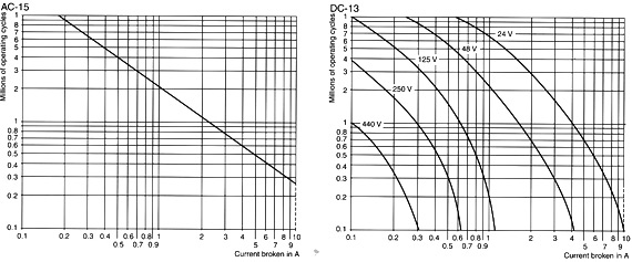
Contact operating power
conforming to IEC 947-5-1 |
a.c. supply categories
AC-14 and AC-15
Electrical life (valid for up to 3600 operating cycles /hour)
On an inductive load such as the coil of an electromagnet:making power (cosf0.7) =10 times the power broken ((cosf0.4) |
d.c.supply category DC-13
Electrical life (valid for up to 1200 operating cycles /hour)
on an inductive load such as the coil of an electromagnet ,without economy resistor,the time constant increasing increasing with the load. |
|
1 million operating cycles
3 million operating cycles
10 million operating cycles |
|
V |
24 |
48 |
115 |
230 |
400 |
440 |
600 |
|
VA |
60 |
120 |
280 |
560 |
960 |
1050 |
1440 |
|
VA |
15 |
32 |
80 |
160 |
280 |
300 |
420 |
|
VA |
4 |
8 |
20 |
40 |
70 |
80 |
100 |
|
|
V |
24 |
48 |
125 |
250 |
440 |
|
W |
96 |
76 |
76 |
76 |
44 |
|
W |
48 |
38 |
38 |
32 |
-- |
|
W |
14 |
12 |
12 |
-- |
-- |
|
|
|
|
Pre:CJX7 series contactors
Next:MC2-388 thru MC2-396 1/2 pole contactors( 30A thru 40A)
David Chang
Managing Director
Morning Sun Electric Co.,Ltd
Add:No.358,Liujiang rd,,liushi town,yueqing city,zhejiang province,China
Tel:0086-577-61586783
Fax:0086-577-61586785
MSN:morsun18@hotmail.com
GMAIL:morsun818@gmail.com
SKYPE:morsun818
Yhaoo messenger:morsun818@yahoo.com.cn